


Still downloading templates?
There’s an easier way. Try a free AI Agent in ClickUp that actually does the work for you—set up in minutes, save hours every week.
Sorry, there were no results found for “”
Sorry, there were no results found for “”
Sorry, there were no results found for “”


Are your network diagrams keeping up with your infrastructure’s complexity? Are your diagrams comprehensive enough to support advanced configurations, yet simple enough for collaborative use across teams? If the answer is no, it is time to rethink your network topology design.
As networks become complex, static or overly simplified diagrams can quickly become outdated or ineffective. This leaves room for miscommunication during deployments, troubleshooting, or upgrades.
A well-crafted network topology diagram can be the solution here, offering insights into data flow, device dependencies, and potential vulnerabilities. In this blog post, we’ll offer a step-by-step guide to create effective network topology diagrams.
Network topology is the systematic arrangement of nodes (devices) and links (communication pathways) within a network. It governs how devices, such as computers, servers, routers, switches, and endpoints communicate, interact, and exchange data.
This arrangement is not merely about connections but the structural and functional dynamics that influence network performance, fault tolerance, and scalability.
Simply put, network topology explains the setup of how devices communicate and share information within a network.
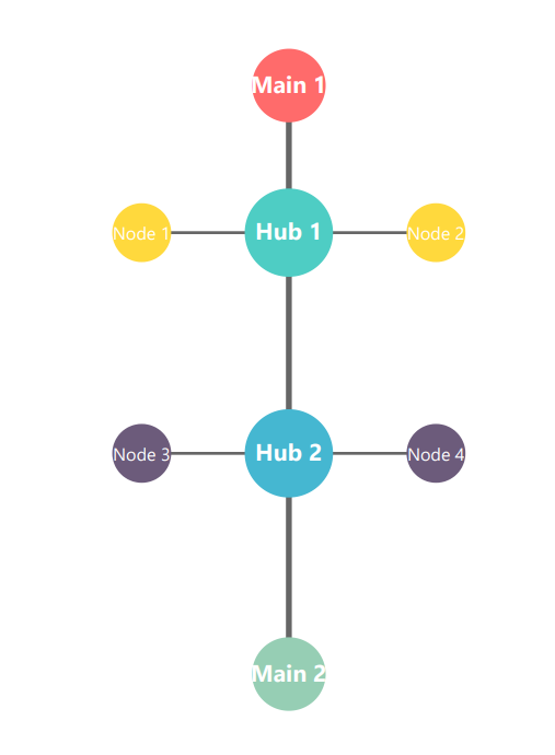
📌 Example: In the below diagram, all the devices are connected to a central hub, which serves as the key point of communication. If one device wants to send data to another, it sends the data to the hub, which then forwards it to another device.
In this case, think of the hub as the network manager or controller, while each device works as an employee who communicates with the manager, but not with each other.
So, at its core, network topology shapes the rules of data traffic, and dictates the data pathways and prioritization within the system.
Network topology directly impacts the network’s performance and efficiency. Here’s how:
Typically, network topologies are of two types—physical and logical.
Physical network topology refers to the actual physical arrangement of devices and cables. For example, the cables running through office ceilings and walls to connect computers to a server room reflect the network’s physical topology.
Mesh topology, Bus Topology, and Ring Topology are some different types of physical topologies (we’ve covered them in detail below).
This maps out how data flows between devices, regardless of physical connections. Ethernet, OSI (Open Systems Interconnection), and TCP/IP (Transmission Control Protocol/Internet Protocol) are the different logical topologies.
🧠 Did you know? The internet was originally developed as a Cold War-era project. In 1969, the U.S. Department of Defense created ARPANET (Advanced Research Projects Agency Network) to ensure that military communication could survive a nuclear attack.
To understand the physical or logical network diagrams better, think of them as the blueprint of a city’s road system. Roads (links) connect different areas (nodes), enabling vehicles (data) to travel between them. Now, you would agree that the way these roads are designed—whether as a grid or circular path will directly affect traffic flow and accessibility, right?
Keeping this example in mind, let’s understand the different network diagram examples.
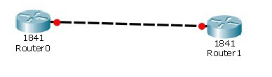
This simple network topology is a direct connection between two network nodes, typically consisting of a transmitter and receiver, with no intermediary devices like switches or routers.
➡️ How this works: The data is transmitted along a single path using various physical media such as fiber optic cables, coaxial cables, or wireless signals, depending on the distance and bandwidth requirements. This topology uses communication protocols like TCP/IP for data transmission.
🌟 Ideal for: Simple, low-latency communications where the interaction between two specific devices is essential, and there is no need for broadcasting or addressing. For example, simple data transfer between two sites.
Bus topology is a linear network structure in which all devices share a centralized communication medium, typically referred to as the ‘bus.’ The bus transmits data packets between devices.
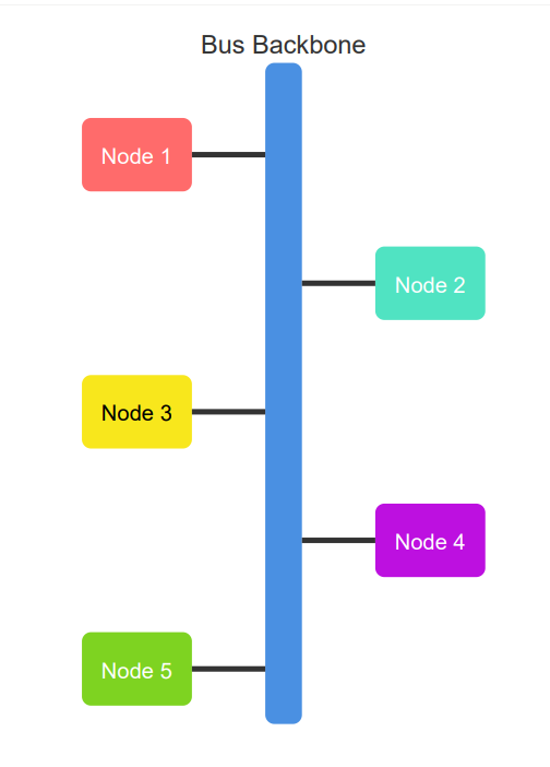
This topology is considered an early design choice due to its simplicity and cost-effectiveness. However, as network traffic increases, bus topology can become inefficient due to its reliance on a single backbone. Moreover, collision risks and troubleshooting complexities increase as more devices are added to the bus.
➡️ How this works: In this structure, data sent by a node is broadcast to all other devices, and each device reads the data but only the intended recipient processes it. The network’s backbone (the bus) is typically a coaxial cable, though other types of cabling, like twisted pair or fiber optics, can be used.
🌟 Ideal for: Low-traffic environments with minimum cabling where devices share a single communication line, ensuring straightforward data transfer.
In ring topology, each device is connected to exactly two other devices, forming a circular data path. Data travels in one direction around the ring, and each node acts as a repeater, forwarding the data to the next device until it reaches its destination.
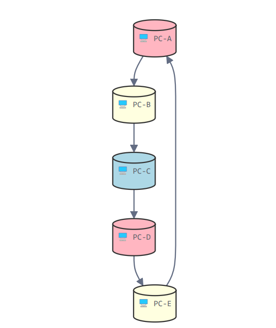
The topology ensures that the data path is always active, but if a single device or link fails, the entire network can be disrupted (unless redundant paths are integrated).
Variations like ‘dual ring’ can mitigate this issue by providing a backup communication path, where data can circulate in both directions.
➡️ How this works: Ring topology often uses token passing as a method to manage the network’s data flow. The token is a special data packet that circulates around the network.
🌟 Ideal for: Environments where data needs to travel in a sequential and structured manner, such as small to medium-sized office networks or industrial control systems.
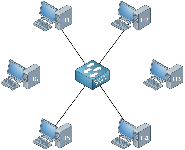
Star topology features a central node (typically a hub or a switch) to which all other devices are connected. This central node controls data traffic and serves as the primary communication point for the network.
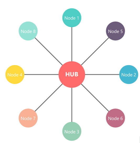
Unlike bus or ring topologies, star topology isolates each node, meaning the failure of a single device does not directly affect others.
Star topology is commonly used in modern Ethernet networks because it simplifies network management and reduces the impact of device failures. It also facilitates scalability, allowing for the easy addition of new devices.
➡️ How this works: All devices (nodes) are connected to a central hub or switch, which manages communication between them. Each device has a direct link to the hub, preventing data collisions and improving network performance.
🌟 Ideal for: Environments where data needs to travel in a sequential and structured manner, such as small to medium-sized office networks or industrial control systems.
A tree topology combines characteristics of bus and star topologies, structuring the network in a hierarchical, branching layout. A central root node connects to a series of secondary nodes (typically in star configurations), and these secondary nodes can connect to additional nodes, creating a tree-like structure.
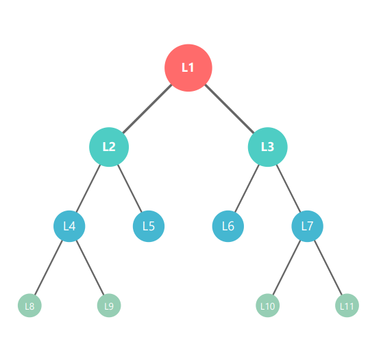
Tree topology allows for more efficient management of large networks by segmenting them into smaller, manageable sub-networks. However, if the root node fails, the entire network can go down.
➡️ How this works: When data is sent from a device, it travels through the hierarchy to reach its destination. The root node manages and directs the traffic between branches.
🌟 Ideal for: Complex networks in large enterprises that require structured organization and scalability.
Mesh topology connects every node directly to every other node, creating multiple paths for data transmission.
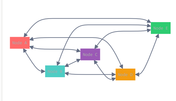
This design significantly increases fault tolerance, ensuring that if one link fails, data can still be transmitted via other paths.
However, mesh topology requires a substantial amount of cabling and hardware to interconnect all devices, leading to higher costs and complexity in large-scale networks.
➡️ How this works: Each device is connected to multiple other devices, creating a web-like structure. Mesh networks require complex routing algorithms to determine the most efficient data path, considering factors like link cost, congestion, and network topology.
🌟 Ideal for: Systems needing real-time data transfer, like video conferencing or live-streaming applications.
✨ Fun Fact: The internet is a mesh topology!
Hybrid topology combines two or more different types of topologies. This approach allows network designers to leverage the strengths of various topologies while mitigating their respective weaknesses.
For example, a hybrid network might use star topology in the central region while employing mesh topology in critical areas.
This topology often carries inflated infrastructural management costs due to high cable and device requirements.
➡️ How this works: Hybrid topologies are highly customizable, enabling the design of a network to meet specific requirements based on location, device types, and fault tolerance
🌟 Ideal for: The use of hybrid topology is ideal for complex networks where different parts of the network have distinct performance, scalability, or redundancy needs.
Now that you understand the benefits and different types of network topology diagrams, let’s see how you can create one:
Start by identifying the size and purpose of your network. This includes understanding and making a list of which devices, connections, and processes you need to represent to achieve a clear and useful diagram.
Next, write down what you aim to achieve with this network diagram. Is it for troubleshooting, planning, or documentation?
Collect details about the network components, including devices (routers, switches, computers), connections, and protocols in use. It ensures every component and connection is correctly represented, and your diagram is both comprehensive and reliable.
Here’s how you can gather relevant information:
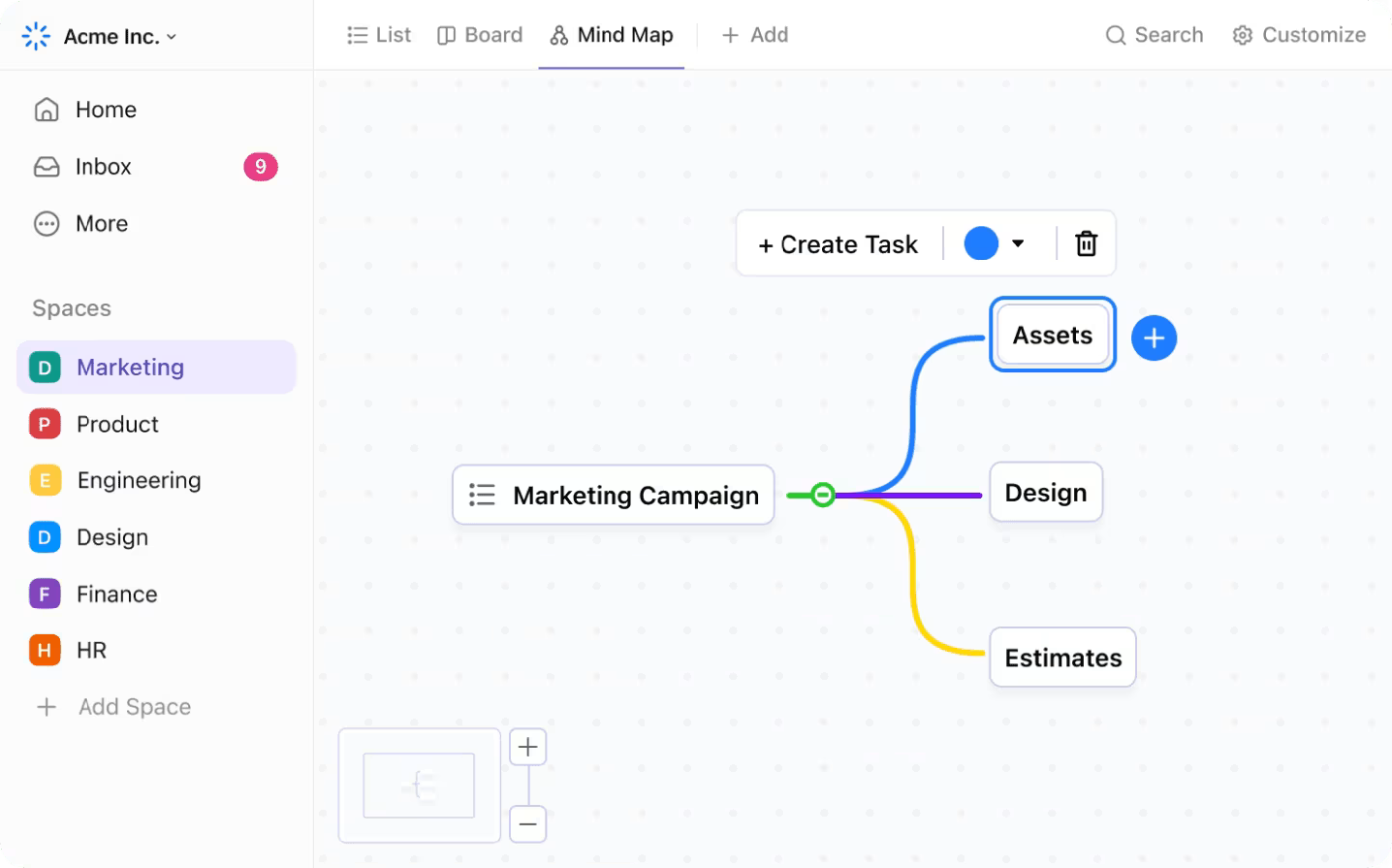
You can create a mind map to arrange all the information. Add major components, such as devices and connections in different branches. Then, include sub-branches for each component. For example, ‘Device’ component can have device names, IP addresses, and bandwidth.
ClickUp, the everything app for work, can help you visualize all the network layers easily with ClickUp Mind Maps. Start with a blank space or use customizable mind map templates for network planning. With ClickUp Mind Maps, you can outline the entire workflow, assign tasks to specific team members to share/review data, and add colors for clarity and visual appeal.
If your mind map looks cluttered, simply use the ‘Re-layout’ option to realign the items.
Once you have all the data, decide which type of topology you want to arrange. Here’s how you can select the right topology type:
| Goal | Topology Type | Reason |
| High Reliability | Mesh | Provides multiple paths for data transmission, ensuring continued operation even if one connection fails |
| Cost-Effectiveness | Bus | Requires less cabling and is easier to set up |
| Scalability | Star | Easy addition or removal of devices without disrupting the entire network |
| High Performance | Star | Dedicated connections minimize data collisions and maximize throughput |
| Flexible Network Design | Hybrid | Combines elements of multiple topologies to meet diverse networking needs and future growth |
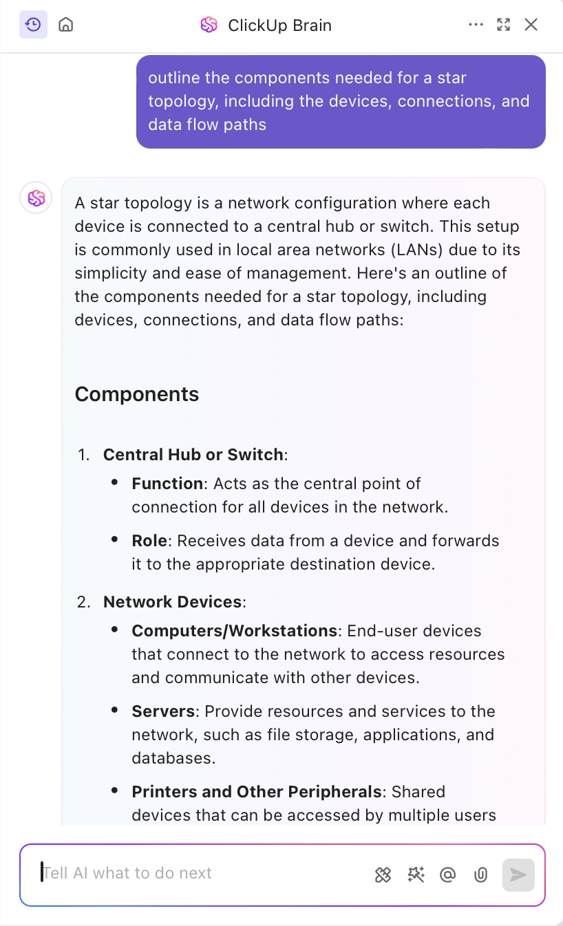
Want to figure out which components you need to create a network topology diagram? ClickUp Brain can help. It’s a powerful AI assistant designed for brainstorming ideas, getting real-time task updates, creating chat summaries, and more.
Just add a detailed prompt asking ClickUp Brain to outline components or create a diagram layout and you’ll have the answer ready in no time.
Now start creating a network topology diagram using a diagramming tool. Look for tools that provide a large canvas to add multiple nodes and visual elements.
Here’s how to create the structure:
If you are looking for a dynamic diagram tool to streamline network management, try ClickUp Whiteboards. It enables you to sketch, draw, and connect your ideas easily. You can drag and drop shapes anywhere on the canvas, add connectors and arrows, and paste sticky notes to provide more context.
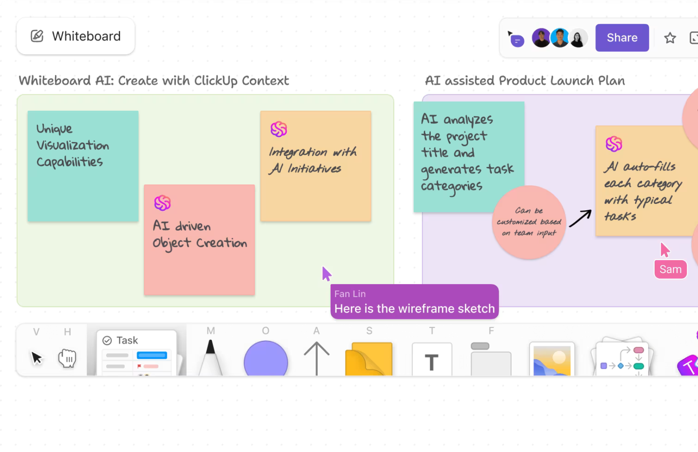
The best part is that you can connect your tasks, docs, and chat in one place. Integrate ClickUp MindMap where you’ve gathered all the information and design your network topology diagram easily.
Plus, multiple team members can work on the diagram simultaneously, making it easier to brainstorm and refine designs. Once the diagram is ready, you can create tasks, related help desk tickets, or IT documentation, directly through the Whiteboard and assign them to team members. If you want to share the diagram with stakeholders, simply export it as an image or PDF.
Learn how to visualize ideas on ClickUp Whiteboards!👇
Review the diagram to ensure all components and connections are accurate. This step prevents future issues caused by overlooked details.
ClickUp for Software Teams makes it easy to gather stakeholder feedback on your diagram. You can add chat directly on the Whiteboard to get inputs from your team. Another simple option is to embed the Whiteboard in ClickUp Chat to get quick feedback.

📮ClickUp Insight: Our survey found that knowledge workers maintain an average of 6 daily connections at their workplace. This probably entails multiple pings back and forth across emails, chat, and project management tools. What if you could converge all these conversations in one place? With ClickUp, you can! It’s the everything app for work that combines projects, knowledge, and chat in one place—all powered by AI that helps you and your team work faster and smarter.
An easier and more efficient way to create a network topology diagram is to use a customizable template. The ClickUp Project Network Diagram Template is made specifically for this purpose. It offers a robust framework for mapping your network’s structure, task dependencies, and project timeline.
You can use this template to map the flow of data across different devices across the organization and streamline workflows. The template also helps you visualize all the resources you need to keep the network up and running.
So, whether you’re planning a new network or optimizing an existing one, ClickUp’s tools empower you to create diagrams that are not only visually compelling but also pivotal to your project’s success.
📖 Read More: How to Start a Project (in 10 Simple Steps)
Network topological diagrams offer a solid visualization of a network’s structure and interconnections. Let’s see how these diagrams help plan, monitor, troubleshoot, and optimize networks:
Topology diagrams act as a detailed network map, providing an immediate overview of all connected devices, locations, and interconnections.
When an issue arises, such as a node failure or latency spike, network administrators can quickly locate the affected segment, trace the data flow, and identify faulty devices or links.
This minimizes trial-and-error methods, significantly reducing downtime.
📌 Example: In a corporate setting, a topology diagram could highlight which floor or department faces a connectivity issue, enabling targeted intervention.
In the lifecycle of a network, capacity planning is a continuous challenge—demand patterns are unpredictable, and technological advancements often outpace existing infrastructure.
Topology diagrams accurately represent the network’s current capabilities, including device count, bandwidth allocation, and link usage. This helps IT teams predict future demands, identify overburdened nodes, and plan expansions efficiently.
📌 Example: If a topology diagram reveals that a core switch is nearing its port limit, administrators can proactively upgrade the equipment to support additional devices, ensuring smooth scalability without unexpected bottlenecks.
Network security relies heavily on an understanding of the IT infrastructure’s layout. Topology diagrams help administrators create IT roadmaps, and pinpoint critical entry points, such as gateways requiring protections like firewalls and intrusion detection systems.
Additionally, the diagrams serve as a foundation for compliance documentation, ensuring that network configurations meet industry standards like SOC 2, GDPR, or ISO 27001. Updated topology diagrams can also demonstrate adherence to security protocols, during audits, mitigating the risk of penalties.
In multi-disciplinary IT environments, where different teams manage hardware, software, and security, effective communication is paramount. Topology diagrams ensure effective team collaboration by offering a shared understanding of the network structure.
This clarity is particularly beneficial for onboarding new team members or collaborating with external consultants.
Network resources such as bandwidth, server capacity, and switch ports must be carefully managed to avoid wastage or underperformance. Topology diagrams reveal underutilized links, redundant devices, and inefficient traffic paths.
📌 Example: If a department is using most of a specific network segment, causing congestion, while other segments are underutilized, network administrators can redistribute the load or reallocate resources.
While network topologies and their mechanisms are super important for communication flow, are there some disadvantages associated with them? The answer is yes. And we have listed a few below:
❗As networks expand, their topologies can become increasingly complex, with numerous devices and interconnections. Effectively representing this complexity in a diagram without sacrificing clarity is a significant challenge.
✅ Solution: Employ industry-standard icons and symbols to represent network components uniformly, enhancing readability.
❗Networks often comprise a mix of devices from various vendors, each with distinct protocols and configurations. Accurately depicting these ‘heterogeneous’ elements in a unified topology diagram requires comprehensive understanding and careful representation to ensure coherence.
✅ Solution: Maintain detailed records of devices, protocols, and configurations to accurately represent diverse technologies. You can also leverage ClickUp’s Whiteboards to collaboratively design and update network diagrams.
❗Topology diagrams can inadvertently expose sensitive information about network structures and vulnerabilities. Ensuring that these diagrams are appropriately secured and access is restricted to authorized personnel is crucial to prevent potential exploitation.
✅ Solution: Restrict access to sensitive diagrams by setting permissions; omit details like IP addresses or device names in shared diagrams to prevent potential security risks.
❗Beyond initial creation, topology diagrams require ongoing maintenance to remain relevant. Establishing protocols for regular updates and version control is necessary to ensure that the diagrams accurately reflect the current state of the network.
✅ Solution: Select tools that offer features aligned with your network’s complexity, such as ClickUp for its versatile diagramming capabilities.
Networks can get complicated fast, with devices connected in different ways and data flowing through countless paths. Without a clear picture of how it all fits together, troubleshooting can feel impossible.
That’s where network topology diagrams come in. ClickUp can be the best partner to help you map out your network in a way that makes sense. It can simplify the process of creating and managing network diagrams. You can visually organize your network architecture, collaborate with your team in real time, and keep everything updated in one central location.
Ready to take control of your network’s complexity? Sign up for ClickUp today and start organizing your network topology with ease.

© 2026 ClickUp

There’s an easier way. Try a free AI Agent in ClickUp that actually does the work for you—set up in minutes, save hours every week.